Adjust Z speed setting of your printer
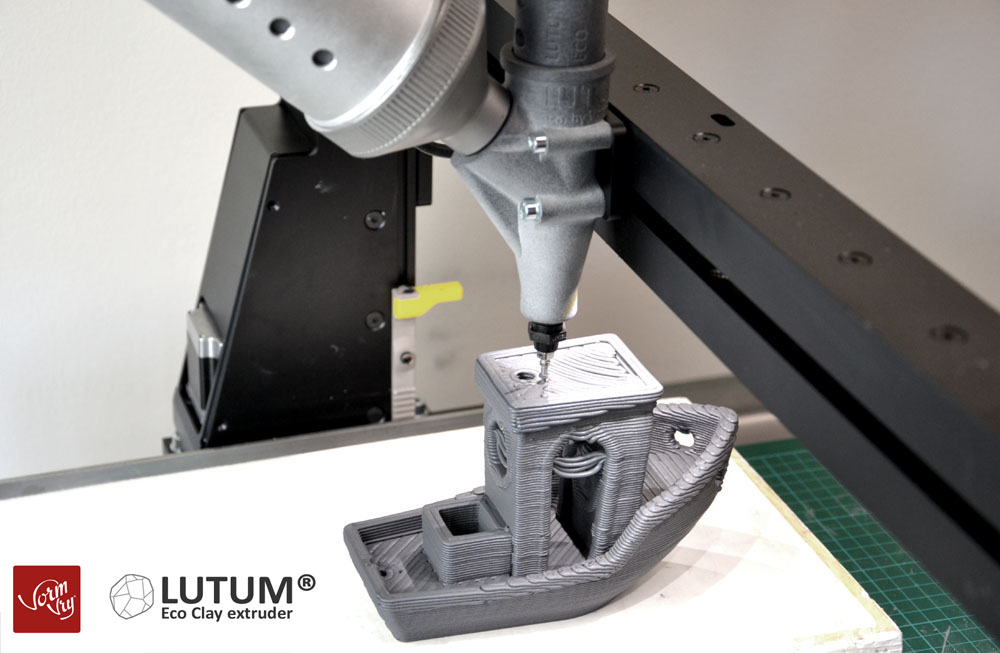
The first models of LUTUM 5 , 5M and 4.6 have shipped! They are equiped with a brand new brain compared to the previous models and we are still adjusting and finetuning behaviour of our machines for optimal performance.
The past few months we noticed that the Up and Down movement of the X arm along the Z direction stalls in some cases. After investigating mechanical and electronic parts it appears most of the stalling can be solved by lubricating the Z axis more often than previously advised.
Adjusting the motion setting of the various macros and and speed limitation settings underlying the Z-movements gives a reliable permanent solution, however, frequent inspection of the Z-spindle lubrication condition is still recommended!
It is easy to adjust
The good news is that it is easy to adjust and at the same time learn a bit about the workings of the hardware-software symbiosis of your machine.
Below are the various steps explained to alter settings on your machine.
All steps are done through the browser interface of the printer. If you have to log on to your LUTUM via the printer acces point you might need to open this website on a different device so you can follow the steps while logged on to your machine.
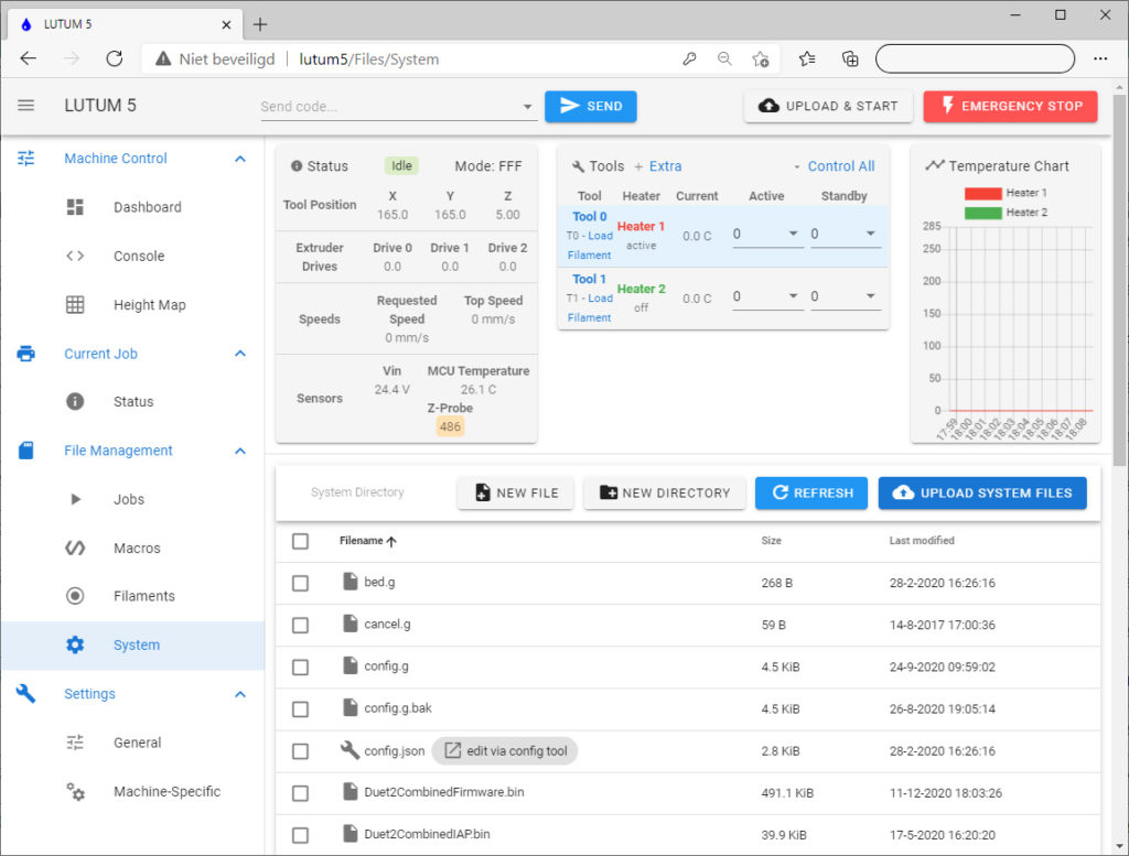
First open your web browser and log on to your printer, then locate the system folder through the LUTUM UI.
In short, the printers hold a set of hard coded instuctions that define the movements of the machine.
These instructions can not be changed.
To define the exact behaviour of your machine the hard-code reads the custom values from the config.g file to know how to excecute Gcode for your specific LUTUM model.
Some instructions depend on separate macros that can also be altered by the user.
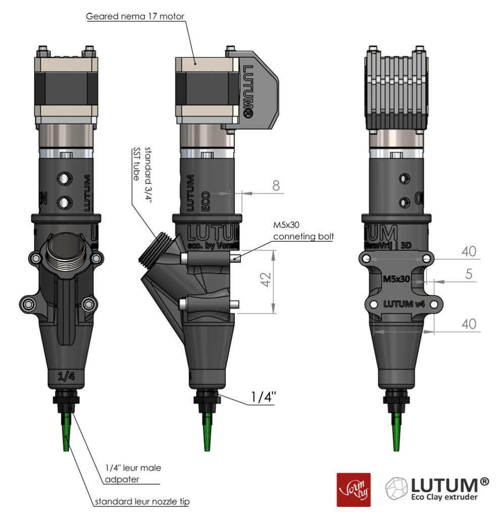
The Pause command, for example, lifts the nozzle 50mm and then moves it to the Y0-X0 location at a certain speed.
By changing the instruction of the Pause.g macro you can change this specific behaviour.
This is also the case for Home-all, homing specific axis and the Resume button.
On the other hand there are also instructions that depend only on the values from config.g. Specifically the ‘move’ commands take speeds and accelerations only from the config.g file. You can have very safe speed values in the macros and still have unsupported speeds in the config.g. As long as speeds in your gcode print file are within range you would not notice the issue until you excecute a move command via the touchscreen or browser interface.
With the steps described in this article the safe upper speed limits are defined in the config.g file.
The macros are adjusted to optimize speeds for their specific use.
Config.g the master file
Locate the config.g file. and click on it to edit.
This is the master instruction file, these values regulate the overall behaviour of your machine.
Make sure you only adjust the values described here.
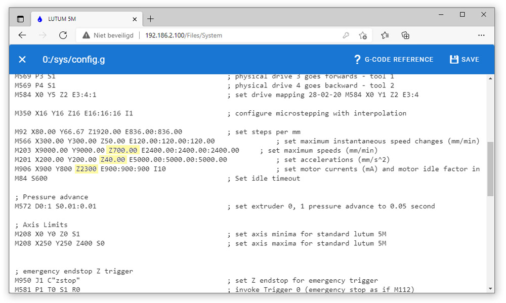
There a 3 values that need adjustment. Locate the lines starting with M203, M201 and M906.
M203 X9000.00 Y9000.00 Z700.00 E2400.00:2400.00:2400.00
M201 X200.00 Y200.00 Z40.00 E5000.00:5000.00:5000.00
M906 X900 Y800 Z2300 E900:900:900 I10
M203 sets maximum limits for speed,
– for Z this should be no more than Z700.00 for LUTUM5 and 5M.
– it should be no more than Z500 for LUTUM4.6 and 4M+.
M201 defines accelerations.
– for Z this should be no more than Z40.00 for LUTUM5 and 5M.
– It should not be more than Z30 for LUTUM4.6 and 4M+.
M906 defines the maximum power (current) the Z motor can receive.
– this can be increased to Z2300 for LUTUM5 and 5M.
– it can be increased to Z1600 for LUTUM4.6 and 4M+.
Alter only the highlighted text, then double check if you only changed those parameters, then save the file and reset your machine.
Homeall.g
This is normally the first instruction you execute when starting the printer.
Locate the homeall.g file. and click on it to edit.
This macro holds the actions it needs to execute when you press the ‘home’ button.
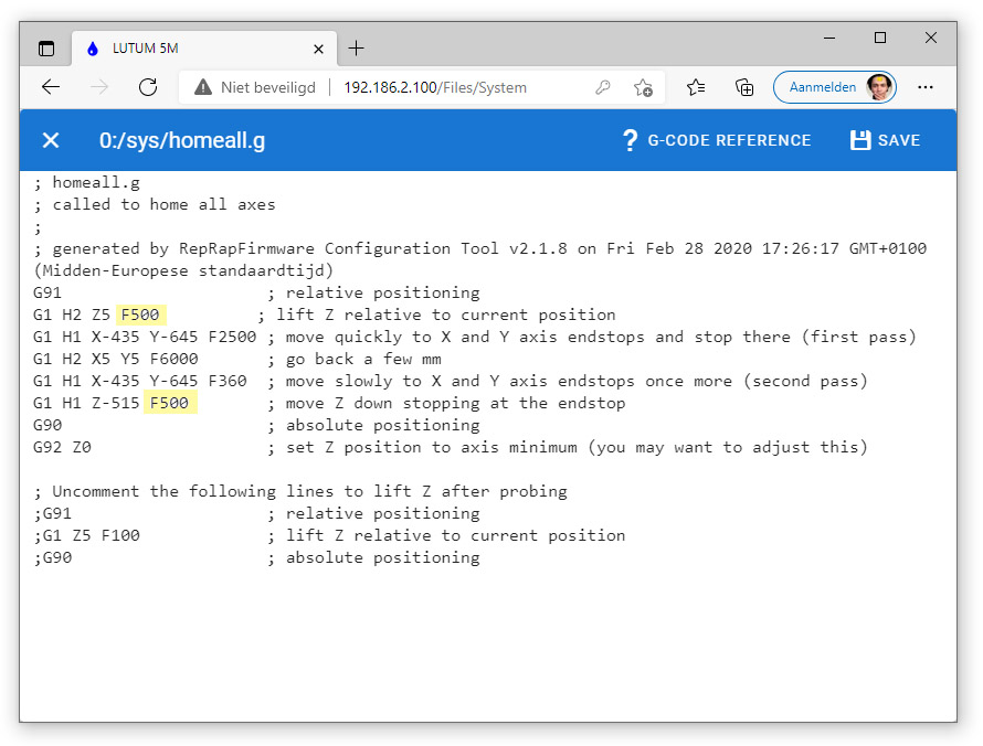
Alter the two values highlited in the picture above then save the file.
homez.g
Locate the homez.g file. and click on it to edit.
This macro holds the actions it needs to execute when you press the ‘home Z’ button .
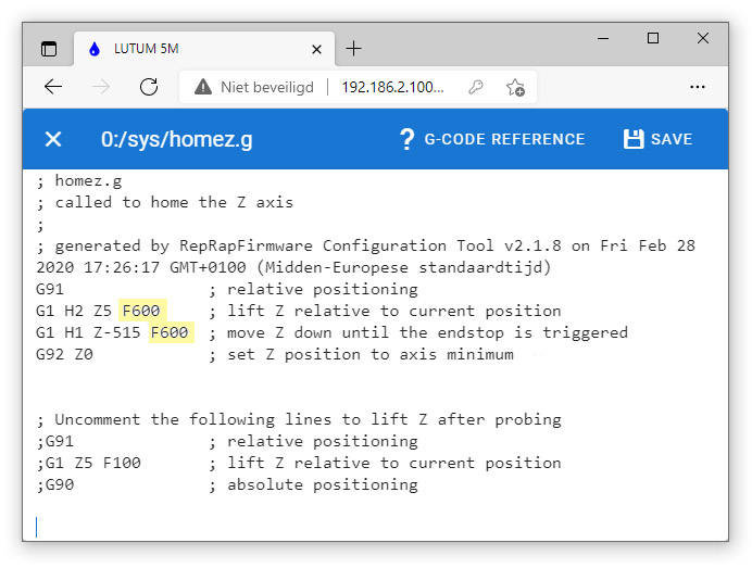
Adjust the highlighted text and save the file..
For LUTUM 4.6 and 4M+ the value should be no more than F500.
Pause.g
Locate the pause.g file. and click on it to edit.
This macro holds the actions it needs to execute when you press the ‘pause’ button during a print.
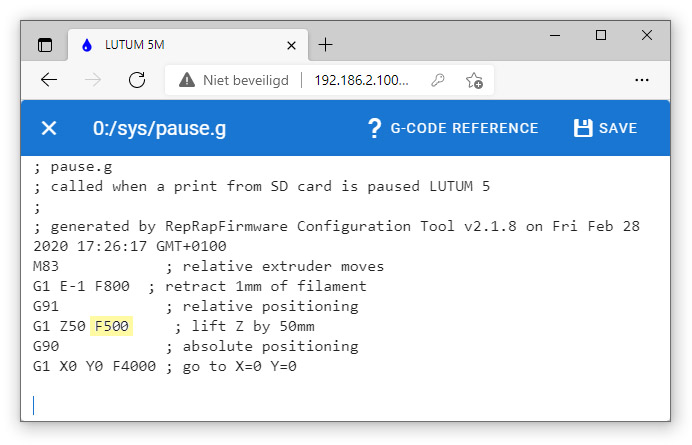
Only the highlighted value needs to be adjusted then save the file.
Resume.g
Locate the resume.g file. and click on it to edit.
This macro holds the actions it needs to execute when you press the ‘resume’ button that can be selected after a pause command.
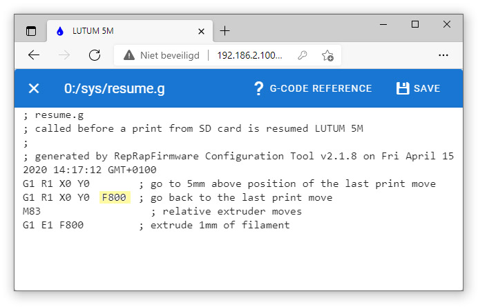
Your resume code could look slightly different.
Alter it to resemble the code above and save the file.
G1 R1 X0 Y0 ; go to 5mm above position of the last print move
G1 R1 X0 Y0 F800 ; go back to the last print move
M83 ; relative extruder moves
G1 E1 F800 ; extrude 1mm of filament
Done
Turn your machine OFF and ON or reset it through the webbrowser with the emergency Stop button. All the new settings come into effect.